POLYVIEW-3D Tutorial
Part 2. Overall structure view
Structure models
When the file contains multiple structural models (e.g., ensemble of
conformations derived using NMR, or alternative docking
models of protein complexes), one can specify the model to
be rendered by entering its number.
Use Lookup button
to see available models.
- This setting is ignored when the option
Animate modelsfrom Animation settings is chosen. - If the model number is not specified, then the first model is used for rendering.
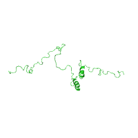
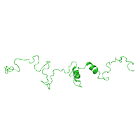
Two panels below illustrate how to select a specific
model by entering its
number from an NMR ensemble of structures, using
C-terminus of the gap junction protein connexin-43
as an example (PDB id 1r5s).
Ligand and solvent data
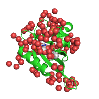
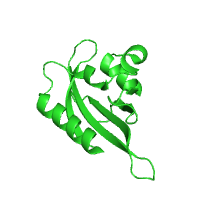
Ligands (chemical moieties defined in HETATM sections
of PDB files) and solvent (primarily water) can
be optionally rendered along with the macromolecular
structure. By default, ligands are shown as spheres, but
they can also be rendered as sticks or balls-and-sticks.
Water molecules are always shown as spheres.
With all ways of rendering, small molecules are colored
using the CPK color scheme (by atom types).
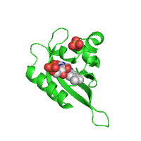
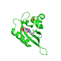
Example below represents crystal structure of the Phot-LOV1 domain from Chlamydomonas reinhardtii in the dark state (PDB id 1n9l), with sulfate anion and flavin mononucleotide ligands shown using sphere and stick models, respectively.
| Rendering ligands as spheres (Default option) |
Rendering ligands as sticks |
|---|---|
|
|
| Showing ligands and water | Hiding ligands and water |
|
|
| Click on respective image to see options used for its rendering. | |
Initial orientation
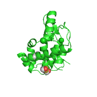
There are several options to change the default projection of the structure, which is defined in the PDB file. One possibility is to specify explicitly the rotation angles (in degrees) around the three main axes (X, Y, Z). These rotations are applied to the original orientation in the order of appearance. However, the trial and error process of setting these angles manually can be tedious. To simplify it, one can use the Java-based Jmol viewer in order to select interactively the desired projection and rotation angles that are subsequently passed to the main submission form.
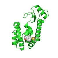
In many instances, it is important to highlight some particular structural elements, e.g., a mutated amino acid residue or a ligand binding pocket. However, the point of special interest typically does not correspond to the center of a rendered image. In POLYVIEW-3D, one can optionally specify the center of view by entering the residue number and/or chain label. If the chain label is given without specifying a residue of interest, the chain centroid will be placed at the center of the view. Alternatively, just like the orientation, the focus can be specified using Jmol, i.e. clicking on the residue of interest to assign it as a center of view will do the trick. The centering of view can be also coupled with zooming.
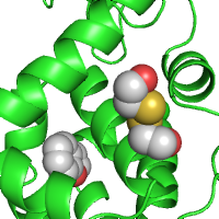
Example below shows how the initial orientation of a protein structure can be adjusted to make its ligand binding pocket more visible. Centering and zooming options are also used in this case to highlight the ligand binding pocket better. Here, interior cavity of T4 lysozyme (PDB id 182l) is shown with two ligand specific pockets that distinguish more rigid chemical structures (benzofuran, in this case, located deeper in the cavity) and more flexible ones (2-hydroxyethyl disulfide, located in the outer pocket).
| Render protein and ligands (Default option) |
Orient the structure | Center and Zoom in the pocket |
|---|---|---|
|
|
|
| Click on respective image to see options used for its rendering. | ||
Last modified: Thu Feb 9 13:40:33 EST 2012
